
Consultation Hotline
+1 (302) 618-8777
+1 (302) 618-8777
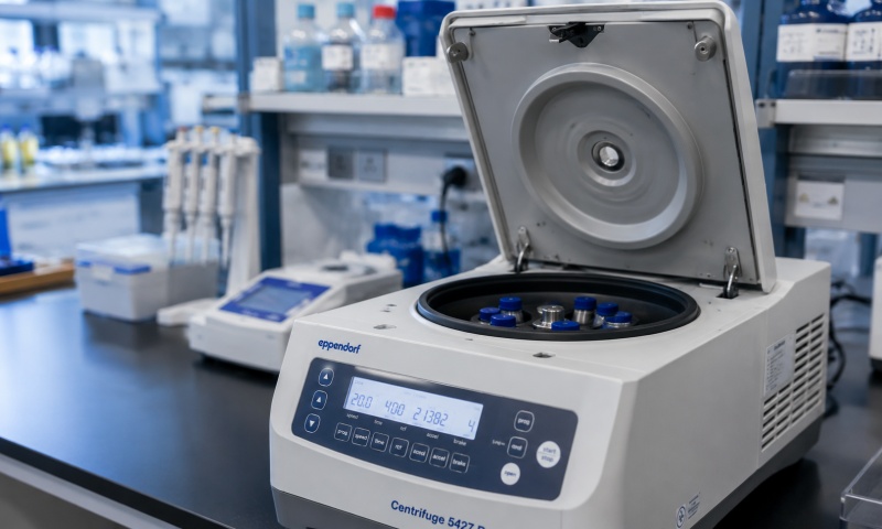
Centrifuges are essential laboratory instruments used in pharmaceutical, biological, chemical, clinical, and research laboratories. By rotating samples at controlled speeds, centrifuges separate components according to differences in density. The rotational speed is one of the most important operating parameters because it directly affects centrifugal force and, consequently, separation performance.
A centrifuge speed failure may appear as an inability to start, failure to reach the set speed, unstable rotation, inaccurate speed display, unexpected speed fluctuations, or an overspeed alarm. These symptoms can originate from mechanical components, sensors, motors, control circuits, power supplies, or software settings. A systematic diagnosis should therefore be performed before replacing components.
When the centrifuge does not rotate after the start command is entered, begin with the basic safety and power checks.
Confirm that the main power supply is available and that the power switch is functioning correctly. Check whether the centrifuge door or lid is completely closed. Many laboratory centrifuges have a door-interlock system that prevents the motor from starting when the lid is open or the locking mechanism is not correctly engaged.
Check for active error messages on the control panel. An emergency-stop condition, imbalance alarm, door-lock failure, or other protection function may prevent the centrifuge from starting.
If the electrical and safety conditions are normal but the motor does not respond, inspect the motor controller, wiring, connectors, and motor assembly.
A common speed-related problem is that the centrifuge starts rotating but cannot reach the programmed RPM.
First verify the selected speed and operating program. An incorrect setting may cause the centrifuge to operate at a lower speed than expected.
Mechanical resistance should then be checked. A damaged bearing, rotor problem, foreign object, or excessive friction can increase the load on the motor and prevent normal acceleration.
The motor and drive system should also be inspected. Depending on the centrifuge design, speed control may use an AC motor, brushless motor, induction motor, or other drive technology. A defective motor controller or drive module can result in insufficient acceleration.
If the instrument reports a motor overload or drive error, do not repeatedly restart it without identifying the cause.
Speed instability can significantly affect laboratory results.
If the displayed RPM repeatedly increases and decreases, first check whether the rotor is correctly installed and balanced. Samples should be distributed according to the manufacturer's recommended balancing requirements.
An imbalance condition can cause vibration and may cause the control system to reduce speed or stop the centrifuge.
If the mechanical load is balanced, inspect the speed-feedback system. Many centrifuges use a tachometer, Hall sensor, optical sensor, encoder, or similar device to monitor rotational speed.
A contaminated or misaligned speed sensor may generate an incorrect feedback signal. Loose connectors or damaged signal cables can produce intermittent speed readings.
Sometimes the rotor speed appears normal mechanically, but the RPM displayed on the control panel is inaccurate.
The first step is to compare the displayed speed with an appropriate independent tachometer when permitted by the equipment manufacturer and laboratory procedures.
If the actual rotational speed differs significantly from the displayed value, the speed sensor or electronic control system may require inspection.
Calibration should be performed using approved procedures. Do not modify internal calibration parameters without appropriate technical documentation because an incorrect adjustment can create a larger speed error.
The rotor is a critical mechanical component of any centrifuge. Damage, corrosion, deformation, or incorrect installation can cause abnormal rotation.
Before operation, inspect the rotor for cracks, corrosion, scratches, deformation, and other visible damage. Rotor buckets and adapters should also be checked for correct installation.
A rotor must be compatible with the centrifuge and operated within its specified maximum speed. Using an unsuitable rotor or exceeding its rated speed can create serious mechanical and safety risks.
If unusual vibration, knocking, or scraping occurs during acceleration, stop the centrifuge according to the appropriate emergency procedure and inspect the rotor and chamber after the rotor has completely stopped.
Excessive vibration is frequently associated with rotor imbalance.
Check that opposing sample positions have appropriate mass balance. Even when the number of tubes is equal, significant differences in sample mass can cause imbalance.
Inspect the rotor mounting system and drive shaft. Dirt or foreign material between the rotor and mounting surface can prevent proper seating.
Worn bearings may also produce vibration. Bearing-related problems are often accompanied by unusual noise, increased mechanical resistance, or abnormal temperature.
If vibration remains after balancing and cleaning, professional mechanical inspection may be required.
A centrifuge that suddenly decreases speed may be responding to a protection function.
Possible causes include rotor imbalance, motor overload, excessive temperature, drive-system faults, door-interlock problems, or unstable power supply.
Check the alarm history if the centrifuge provides diagnostic information. The alarm code can help identify whether the shutdown originated from the motor, speed feedback, temperature protection, or another subsystem.
The centrifuge should not be returned to normal operation until the underlying problem has been identified.
The speed sensor is one of the most important components in closed-loop speed control.
Depending on the centrifuge design, the sensor may detect magnetic, optical, or encoder-based signals. Inspect the sensor position and surrounding area for contamination or physical damage.
Check the sensor cable and connectors for loose connections, oxidation, broken wires, or insulation damage.
If the sensor signal is unstable, the controller may interpret the rotor speed incorrectly. This can lead to speed alarms, unstable rotation, or automatic shutdown.
Sensor replacement should use a compatible component and follow the manufacturer's installation and adjustment requirements.
If the rotor, bearings, speed sensor, and mechanical system appear normal, the motor and drive electronics should be considered.
Inspect the motor for abnormal noise, overheating, burning odor, or excessive vibration. Check electrical connections and the motor controller according to the service documentation.
A faulty drive module may cause slow acceleration, unstable speed, or complete failure to rotate.
Electrical measurements should only be performed by qualified personnel using suitable instruments and appropriate safety procedures.
A systematic repair process can be summarized as follows:
Record the centrifuge model, rotor type, speed setting, and error code.
Disconnect or isolate the equipment according to the manufacturer's safety procedure.
Check the power supply and safety interlocks.
Inspect the rotor, chamber, mounting system, and drive shaft.
Verify sample balance and rotor installation.
Check bearings and mechanical resistance.
Inspect the speed sensor and signal wiring.
Examine the motor and drive controller.
Perform calibration or speed verification when required.
Conduct a controlled test run before returning the centrifuge to service.
Regular maintenance can significantly reduce speed-related failures.
Clean the rotor and chamber according to the manufacturer's recommendations. Remove sample residue and prevent corrosive substances from remaining on metal surfaces.
Inspect rotors regularly for corrosion and damage. Rotors have defined service lives in many applications and should not be used indefinitely simply because they appear visually acceptable.
Check the condition of bearings, drive components, sensors, cables, and connectors during scheduled maintenance.
Speed verification and calibration should be performed at appropriate intervals based on equipment usage, laboratory requirements, and manufacturer recommendations.
Centrifuge speed failures can originate from incorrect settings, rotor imbalance, mechanical resistance, bearing wear, speed-sensor faults, motor problems, drive-controller failures, or electrical and safety-system issues. Correct diagnosis requires a step-by-step approach rather than immediate component replacement.
The recommended principle is to inspect the system from simple external factors to more complex internal components: first verify the operating settings and safety conditions, then inspect the rotor and mechanical system, followed by the speed sensor, motor, and control electronics.
For pharmaceutical and other regulated laboratories, all maintenance, repair, calibration, and performance-verification activities should be documented. A properly maintained centrifuge provides more stable rotational performance, reduces unexpected downtime, and helps ensure reliable and reproducible laboratory results.