
Consultation Hotline
+1 (302) 618-8777
+1 (302) 618-8777
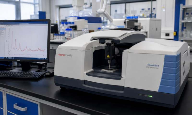
Gas chromatography (GC) is widely used for the qualitative and quantitative analysis of volatile and semi-volatile compounds. A gas chromatograph contains several critical components, including the carrier gas system, injector, column, oven, detector, electronic control system, and data-processing software. When any component operates abnormally, the instrument may show unstable baselines, abnormal pressure, poor peak shape, retention-time drift, or failure to detect samples. Proper troubleshooting requires a systematic approach rather than replacing components randomly.
Carrier gas problems are among the most common GC faults. If the carrier gas pressure is too low, unstable, or completely absent, check the gas cylinder, regulator, tubing, filters, and instrument gas connections first.
Make sure the gas cylinder contains sufficient gas and that the regulator is correctly adjusted. Check all connections for leaks using an appropriate leak detector. A blocked gas filter, capillary tubing, or inlet liner can also restrict gas flow. If electronic pressure control is installed, verify the pressure settings and confirm that the pressure sensor is functioning correctly.
For systems using hydrogen as carrier gas, special attention should be paid to leak detection and safety procedures.
A drifting or noisy baseline can significantly affect quantitative results. Several factors may contribute to this problem, including detector contamination, column contamination, unstable gas flow, temperature instability, and electronic interference.
First, allow the GC to reach thermal equilibrium. Check whether the oven and detector temperatures remain stable. Inspect the carrier gas supply and replace contaminated gas filters when necessary. If the detector is dirty, follow the manufacturer's cleaning and maintenance procedure.
Column contamination is another common cause. If the column has accumulated nonvolatile materials, appropriate conditioning or replacement may be necessary. However, the maximum conditioning temperature specified for the column should never be exceeded.
Peak tailing, fronting, broad peaks, or split peaks may indicate problems with the injection system, column, sample, or analytical conditions.
A contaminated or damaged inlet liner can cause poor vaporization and peak distortion. Replace the liner and septum when they become contaminated or worn. Check whether the injection volume is appropriate for the inlet and column capacity.
Peak tailing may also result from active sites in the inlet or column, while peak fronting can occur when the column is overloaded. If peaks become progressively broader, inspect the column for contamination, leaks, dead volume, or deterioration.
Unexpected changes in retention time are often associated with carrier-gas flow, temperature, or column conditions.
Check the carrier-gas pressure and flow rate first. Verify that the oven temperature program is correct and that the oven temperature sensor is operating properly. A leak near the injector or column connection can also alter the effective flow through the column.
If retention times gradually increase during routine operation, column contamination or degradation should be considered. Consistent maintenance and proper sample preparation can help minimize these problems.
When the chromatogram shows no peaks or signals are significantly weaker than expected, check the entire analytical path systematically.
Confirm that the sample was prepared correctly and that the autosampler or manual injector is functioning properly. Check the inlet temperature, carrier-gas flow, detector temperature, and detector gas flows. For flame ionization detection (FID), verify that hydrogen and air supplies are available and that the flame is ignited.
For thermal conductivity detectors (TCD), check the reference and makeup gas conditions according to the instrument configuration. Detector contamination, incorrect gas flow, or damaged detector components may also cause weak signals.
The injector is directly exposed to samples and therefore requires regular maintenance. Common injector problems include septum leakage, blocked liners, poor vaporization, and contamination.
A damaged septum can cause gas leakage and unstable retention times. Replace the septum according to the recommended maintenance interval. Inspect the liner for deposits and replace it if necessary. The inlet temperature should also be appropriate for the sample and solvent to ensure efficient vaporization without causing thermal degradation.
If the oven cannot reach the programmed temperature or displays unstable temperatures, inspect the heating system, temperature sensor, fan, and ventilation conditions.
Make sure the oven door is completely closed and that the cooling or exhaust system is not obstructed. If the temperature fluctuates significantly after the instrument has reached equilibrium, the temperature sensor, heater, or control circuit may require professional inspection.
Regular preventive maintenance is one of the most effective ways to reduce GC failures. Establish a maintenance schedule covering gas filters, septa, liners, syringe components, detector parts, column connections, and leak testing.
Operators should also maintain appropriate laboratory conditions, including stable temperature, clean surroundings, reliable gas supplies, and suitable electrical power. Samples should be properly filtered or prepared to reduce contamination.
Gas chromatograph troubleshooting should follow a logical sequence: identify the symptom, determine whether the problem is related to gas supply, injection, column, temperature control, detector, or electronics, and then test each possible cause systematically. Common problems such as unstable pressure, baseline noise, poor peak shape, retention-time drift, weak signals, and injector contamination can often be resolved through proper inspection and routine maintenance. For faults involving electronic circuits, detector damage, pressure-control modules, or other critical components, qualified service personnel should perform the repair. Accurate diagnosis not only restores instrument performance but also helps prevent repeated failures and improves the reliability of analytical results.